

U & L Shaped Snap-Fit Design
| Overview |
Occasionally a designer will not be able to design a cantilever snap-fit configuration with a strain below the allowable limit of the intended material. This is usually due to limited packaging space which can restrict the length of the snap. This is the ideal time to consider using either an "L" shaped snap or "U" shaped snap.
| The "L" shaped snap is formed by designing in slots in the base wall which effectively increases the beam length and flexibility compared to a standard cantilever beam. This allows the designer to reduce the strain during assemble below the allowable limit of the selected material. It should be noted that adding a slot to the base wall may not be acceptable in some designs for cosmetic or air flow concerns. | |
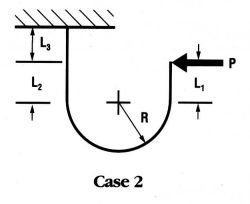
| The "U" shaped snap is another way to increase the effective beam length within a limited space envelope. With this design, even materials with low allowable strain limits (such as highly glass-filled materials) can be designed to meet assembly requirements. The "U" shaped design usually incorporates the undercut on the outer edge of the part to eliminate the need for slide in the mold, unless a slot is acceptable in the wall from which the snap projects. | |
| L Shape Formulas |
The following formulas are used in the L shape snap-fit calculations:
 |
 |
 |
| U Shape Case 1 Formulas |
The following formulas are used in the U shape case 1 snap-fit calculations:
 |
 |
 |
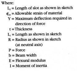
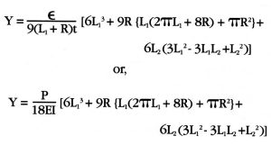
| U Shape Case 2 Formulas |
The following formulas are used in the U shape case 2 snap-fit calculations:
 |
 |
 |
Copyright� 2006 BASF Corporation